Bramah Locks and Keys
Joseph Bramah patented his distinctive cylindrical lock in 1784. Unlike conventional locks of the period, the Bramah mechanism used a tubular key to depress a series of spring-loaded steel sliders to different predetermined depths. Only when the notches in every slider were correctly aligned could the central cylinder rotate and operate the bolt.
Bramah continued to refine the design, patenting further improvements in 1798. The principle proved remarkably successful and the lock became widely used on travelling cases, dressing cases, jewellery boxes and other valuable fitted boxes throughout the nineteenth century.
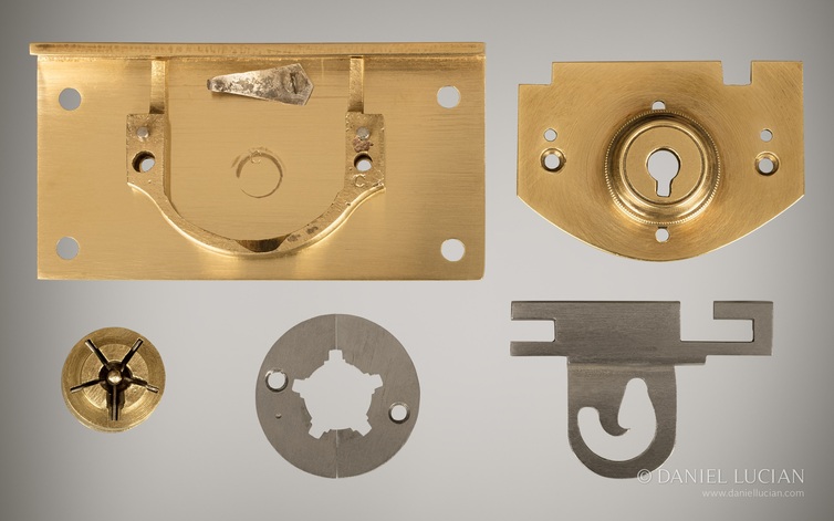
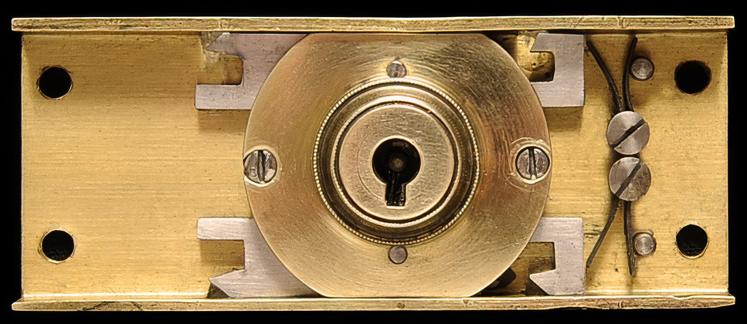
Components of a Bramah Lock
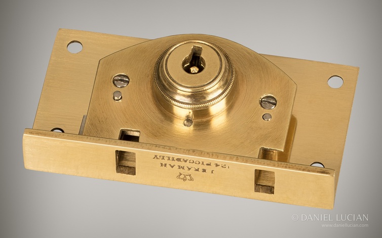
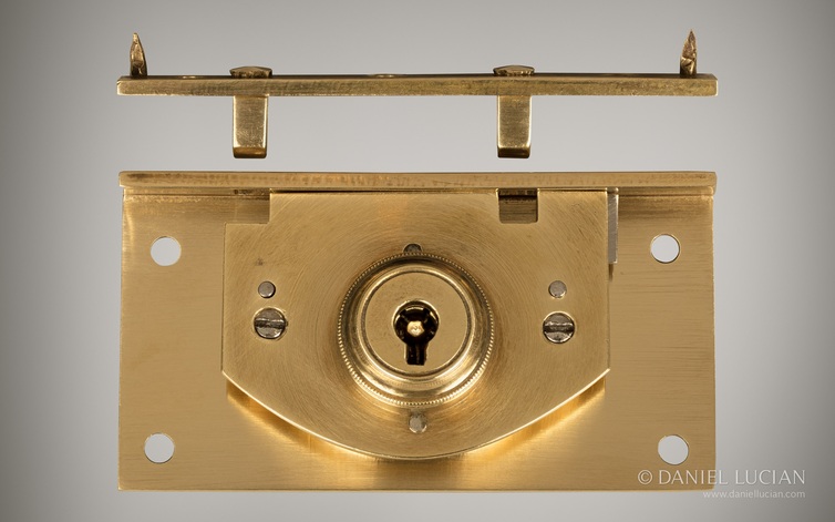
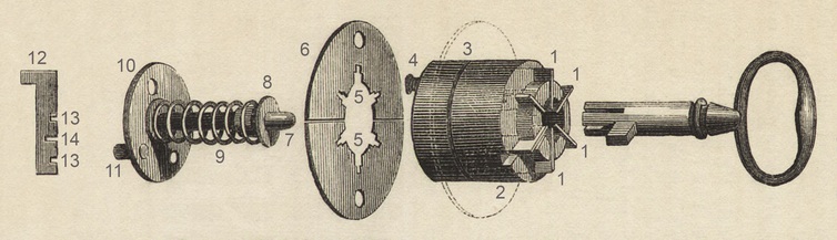
- A typical Bramah box lock can be dismantled into the following principal components:
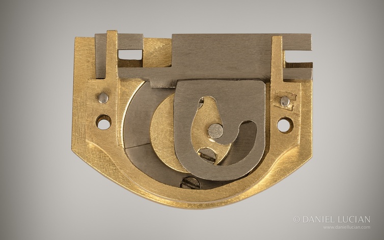
- a brass back plate and outer lock surface plate;
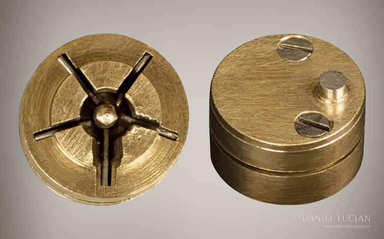
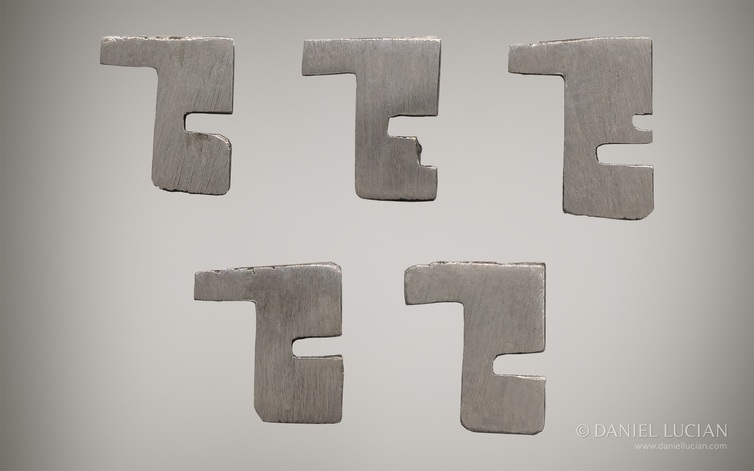
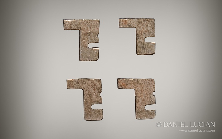
- a turned brass central cylinder containing a series of intricately cut, folded steel sliders;
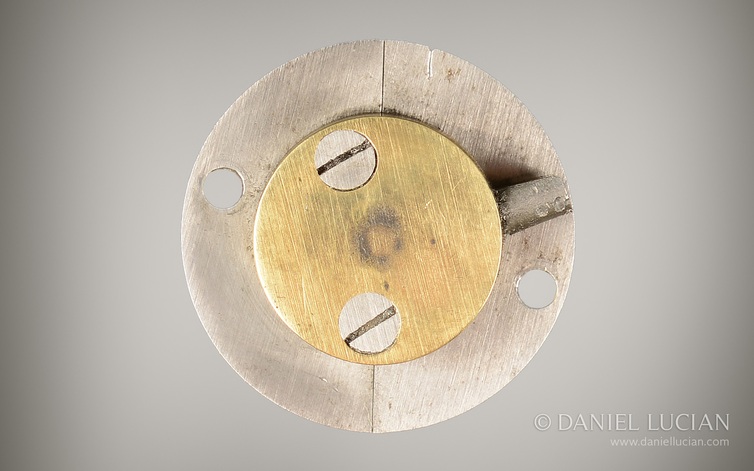
- a cylinder back plate with central pin, spring and brass collet;
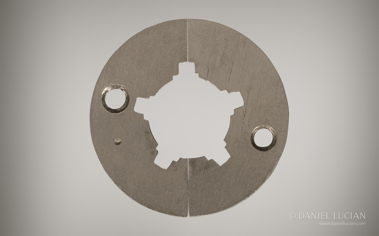
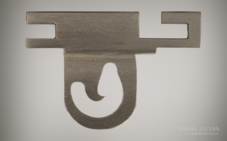
- two semicircular steel locking plates which engage with the central cylinder and sliders;
- a turned brass lock mount and front aperture;
- a brass or steel sliding bolt, sometimes fitted with a guide plate;
- a brass bolt-support bracket attached to the back plate where required;
- a mounted steel spring;
- a brass or steel link plate engaging with the sliding bolt;
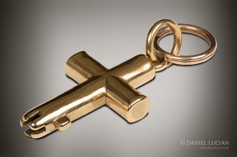
- a tubular key with bits cut to varying depths around the end of its barrel.
Most Bramah box locks have a stud on the rear of the cylinder back plate which engages with the bolt mechanism. Self-locking versions, together with some standard locks, instead use a projecting cylinder arm which acts directly upon an incised section of the sliding bolt.
The arrangement of the bolt spring also varies. On many standard locks the spring is mounted beneath the sliding bolt, while on self-locking versions it is generally positioned to the side so that it can return the bolt automatically to the locked position.
Identifying and Dating Bramah Locks
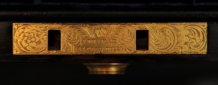
The wording stamped or engraved onto the lock surface plate is particularly important when identifying an original Bramah-made lock and can often provide a useful indication of date.
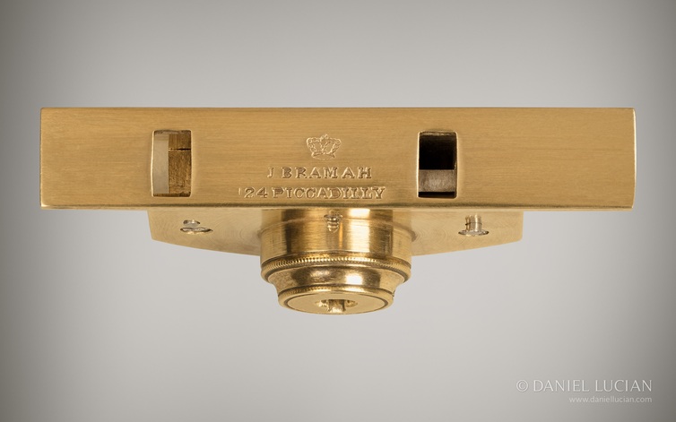
From 1798, original Bramah lock plates can be found marked I. Bramah or J. Bramah, often accompanied by the monarch’s crown. Other examples are marked Bramah – 14 Piccadilly or Bramah – 124 Piccadilly, with or without the crown.
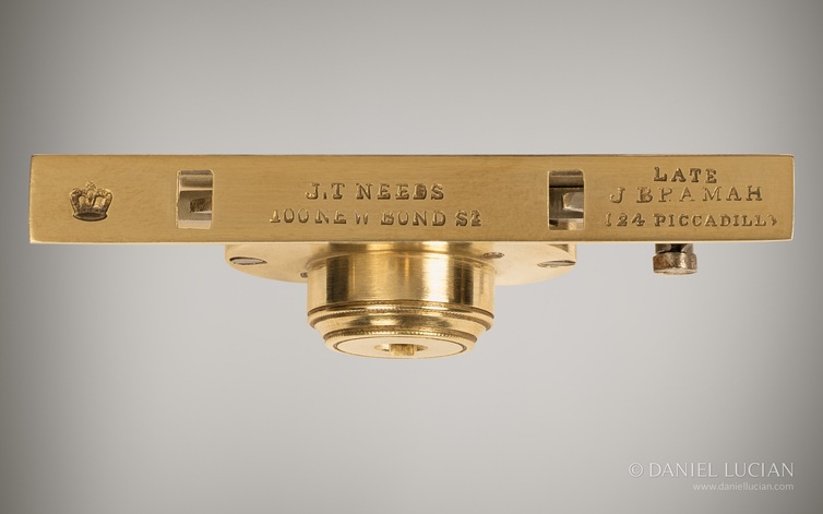
After J. T. Needs & Co. acquired the Bramah lock business in 1871, the markings changed with the firm’s successive addresses:
- J. T. Needs & Co. Down Street, Piccadilly, W — 1871–c. 1875
- J. T. Needs & Co. 128 Piccadilly — c. 1875–1887
- J. T. Needs & Co. 100 New Bond Street – Late J. Bramah 124 Piccadilly — 1887–1904
These later markings are normally accompanied by the monarch’s crown.
Blank lock plates, and examples marked only Bramah Patent, Bramah’s Patent, Patent or Bramah – London, are generally associated with locks manufactured by other makers using the Bramah principle after the relevant patent protection had expired. They should not therefore automatically be regarded as locks manufactured by Bramah themselves.
This makes the wording and address on the lock plate especially valuable when assessing both the originality and approximate date of a surviving box.
Operating a Bramah Lock
- When the tubular key is inserted through the front aperture, it is guided over the central pin. The differently cut bits around the end of the key then engage with the spring-loaded steel sliders and press each one inward by a predetermined amount.
- Each slider contains a precisely positioned notch. When the correct key is fully inserted, these notches align in the same plane, allowing the two semicircular locking plates surrounding the cylinder to move unobstructed. The central cylinder can then rotate.
- If even one slider is positioned either too high or too low, its solid section continues to obstruct the locking plates and prevents the cylinder from turning.
- The key is then turned anti-clockwise, rotating the central cylinder. On many standard locks, a stud on the rear of the cylinder back plate engages with a guide plate attached to the sliding bolt. On self-locking examples, a projecting cylinder arm engages directly with an incised section of the bolt.
- As the cylinder turns, the sliding bolt travels across the back plate, generally from right to left, until it reaches the locked position.
- The key can then complete its rotation back to the original insertion point. The spring pressure acting behind the sliders causes the key to project slightly from the front aperture, allowing it to be removed.
- Unlocking simply reverses the sequence: the key is inserted and fully depressed, the sliders are correctly aligned, and the key is turned in the opposite direction to retract the bolt before returning to its starting position.
Self-Locking Bramah Locks
Self-locking Bramah locks operate on the same slider principle but use a spring-loaded bolt which automatically returns to the locked position.
To open the box, the key is inserted and turned clockwise through a relatively short movement, typically around 45–90 degrees. This rotates the cylinder arm, which engages with the sliding bolt and pushes it back against the mounted steel spring, disengaging the lock.
As soon as pressure on the key is released, the spring drives the bolt back into its locked position. The box therefore locks automatically when closed without requiring the owner to turn the key through a complete locking cycle.
This self-locking arrangement became particularly useful on travelling, jewellery and dressing cases, where the owner could close the box knowing that the lock would automatically re-engage.







Bramah Master Keys
Bramah also produced master-key systems in which several locks could each retain their own individual key while also being operated by a single master key. This was achieved by incorporating an additional set of corresponding notches into the steel sliders of each lock: the ordinary key aligned one set of notches, while the master key aligned the second.
One particularly elaborate form was the Cross Master Key, examples of which were made in 18-carat gold for households with multiple boxes fitted with Bramah locks.